KPL Keypads come in 6 and 8 button configurations.
By changing the faceplate on the KPL, the button config can be modified as desired, and the PH Insteon Explorer>KPL Config Tab can be used to modify the KPL’s Properties to match. Newer models of the KPLs are now ordered and configured for specific usage.The button numbering on a KPL is easily confusing, but the following diagram should clear things up...

All keypads have 8 switches numbered from 1-8. The 6-button keypad just has wide buttons on the top/bottom rows that simultaneously activate the 1-2 (top) and 7-8 (bottom) switches when pressed.
NOTE: a 6-button keypad uses the top and bottom button pairs to create an On/Off switch function. ALL of these 4 combined buttons (1,2,7,8) are referred to collectively as button "1" and are associated directly with the KPL device ID just as a normal Insteon wall switch's top/bottom switch presses are linked to the "0" button to control the device.
Controlling KPL Associated Device
Insteon "on/off" commands for the KPL's attached device are just sent to either the 6 or 8 button KPL, as a normal wall switch would be treated, eg, ph_insteon("MID CHANDELIER",ifaston,0). By defining the 6-button keypad, this way it allows control to always be the same for both types of KPLs. Associated device control is always to "1" and the remaining buttons control their respective linked devices.
Via PowerHome, or Insteon manual controller/responder direct linking the non-button1 keys can be used to control other devices, or the individual key lights can be used merely to show "status" of other devices (eg, garage door open).
Controlling KPL Button Lights
Buttons on a KPL are controlled with Insteon Group, or Group Cleanup commands. (eg, ph_insteongroup; ph_insteongroupcu).
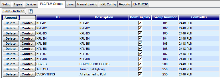
First Define a PLM Group to assign an ID to the PLM Controller link which can be used in Macro commands. Define a Macro which turns the KPL button ON or OFF. As illustrated below, eight buttons have been assigned individual Group Numbers. These may be used with any KPL, as the PH control functions specify both the Device ID as well as a button number.
To control a KPL button, links must be created in the Insteon Explorer>Links tab just as any controller/responder link would be set up between any two linked Insteon devices.
For example, using the above Group ID's to light button 4 on a KPL keypad in the bedroom to indicate the garage door was open,the following would do it...
ph_insteongroupcu("KPL-B4","BEDROOM_KPL",ifaston)
If there were multiple KPLs, all with the Garage Door Open status indicated on button-4 then instead of the specific KPL control offered by ph_insteongroupcu(), the broader ph_insteongroup() function could be used. This will light button-4 on all KPLs that have their button four assigned to "KPL-B4" (in point-of-fact such specific usage would be better done with a specific group name like "GDR_STATUS" assigned to its own unique Group Number such as "204". This also offers the advantage that the Status light could then be on any KPL button that was linked to that Group ID. {See more on linking below})
For example...
ph_insteongroup("GDR_STATUS","ifaston",0)
Creating Controller/Responder Links
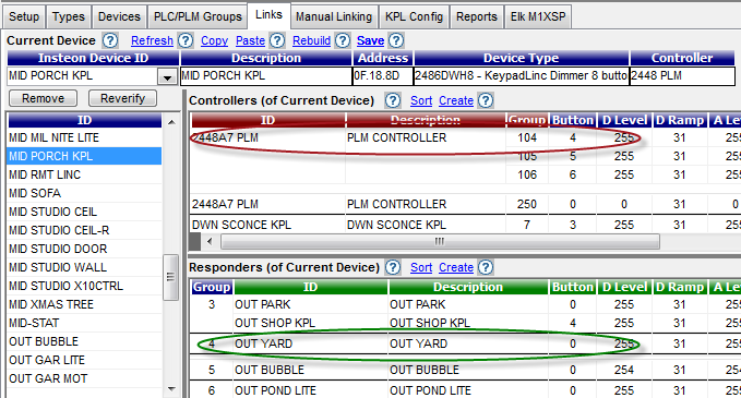
In the example below, links have been created in the "MID PORCH KPL" with the PLM as the Controller and various other switches and KPLs as Responders. In the Controllers frame, the Group 104 entry allows button-4 on the porch KPL to be controlled by PH functions (eg, ph_insteongroupcu("KPL-B4","MID PORCH KPL ",ifaston) while the link for Group 4 (which is button-4 on this KPL) controls the OUT YARD light.
Understanding KPL Groups
When linking KPLs to each other the Group and Button meanings are as follows:
For Controllers the "Group" number will be the button number on the sending KPL and the "Button" number will be the affected button on the receiving KPL.
For Responders the "Group" # will be the button# on this selected KPL and the "Button"’ # will be the button on the responding Device(0) or KPL(#).
In most cases the Button# will just be “0" for all controllers and responders except KPLs..

With the release of PH version 2.1.5, the management of KPL setups has been moved to the Insteon Explorer>Devices tab.
To open the KPL configuration window, click on the Options button next to the KPL Device. This will open the Insteon Options Window. Here you can configure the KPL to be a 6 or 8 button device; set the On Level and Ramp Rate for the Button 1 (master KPL device); and also allow you to set KPL Buttons in Toggle/On-Off mode; and control the button back-lighting actions. ...

To set a KPL Button to be a Toggle/On/Off button with every press, use the Explorer>PLC/PLM Groups>Control window to turn the desired KPL buttons on/off.
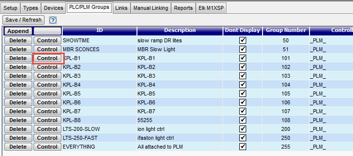
Set the buttons you wish to set as non-toggle ON to be "On" and the buttons you wish to set as non-toggle OFF to be "Off." Save changes.
Then using the Explorer>Devices>Options button, (per 2nd image above) set the appropriate buttons from toggle to either non-toggle on or non-toggle off. It doesn’t matter (other than the button is not set to be toggle) as the button will be set as non-toggle on or non-toggle off based upon the current status of the button’s lights. Press Save/Refresh.
Then in order for the KPL to “see” the changes, it must be power cycled to set the changes into ROM. To do this, pull the KPL Air Gap tab out for 10 seconds, then push it back onto the ON position, or turn the circuit breaker/fuse off/on for the circuit.
What the LED On and LED Off checkboxes control is the status of the other KPL buttons when the button in which the checkboxes reside is controlled.
For instance, take “Button 1" . If you placed a check in LED On for 3 and a check in LED Off for 5, then when you manually control button 1, button 3 will be lit and button 5 will be off. It usually used to make mutually exclusive buttons for a scene. Say button 3 is scene full on, button 4 is scene 75% on, button 5 is scene 50%, and button 6 is scene 25%. In this case, if you press button 4 (scene 75%), you would want the other 3 buttons (3,5,6) to turn off.